


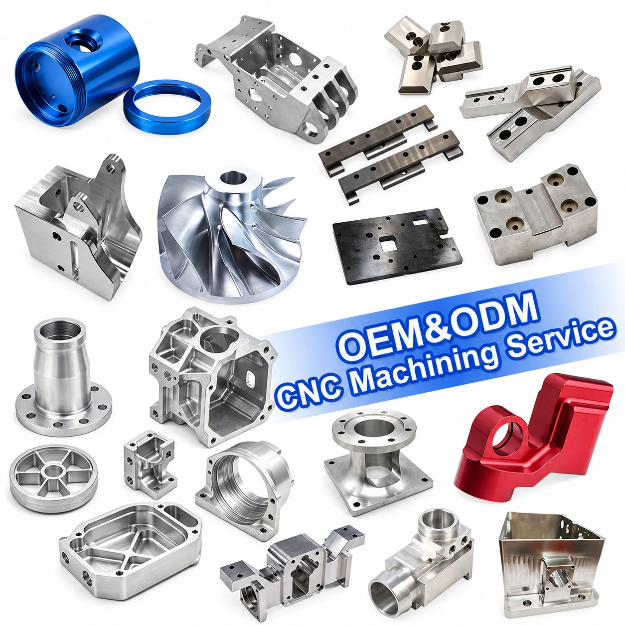
Rapid Prototyping, OEM ODM CNC Machining Service
| Visible product family | Observable features | Possible project role |
|---|---|---|
| Complex CNC housings | Cavities, ribs, bores, mounting holes and external faces | Equipment housings and functional prototypes |
| Blue cylindrical housing | Threaded face, circular body, bore and colored exterior | Enclosure, adapter or interface component; exact use to confirm |
| Structural brackets | Angled walls, holes, ribs and mounting faces | Automation, fixtures and equipment frames |
| Red finished bracket | Curved exterior, bore and colored surface | Custom mechanical support or interface |
| Multi-hole plates | Through holes, slots and flat datum surfaces | Fixtures, mounting plates and tooling |
| Flanged housings | Circular flange, bore and bolt-hole pattern | Adapters, seals and machine interfaces |
| Threaded fittings | Internal or external thread and stepped body | Connectors, adapters and fluid/mechanical interfaces |
| Curved or impeller-like parts | Blades, curved surfaces and central hub | Flow, motion or prototype components; function to confirm |
| Machined blocks | Pockets, counterbores, ribs and intersecting faces | Jigs, tooling and industrial parts |
| Sleeves and rings | Concentric diameters, bores and seating surfaces | Spacers, collars and assembly interfaces |
| Small turned components | Steps, grooves, bosses and threaded ends | Precision mechanisms and replacement parts |
![Rapid Prototyping, OEM ODM CNC Machining Service 6]() Process Capability Matrix
| Process | Typical features | Suitable project phase |
|---|---|---|
| CNC milling | Pockets, slots, holes, flats, ribs, steps and irregular profiles | Prototype, first article and production |
| CNC turning | Shafts, sleeves, rings, bosses, bores and threads | Prototype, replacement and repeat supply |
| CNC 5-axis machining | Angled faces, compound surfaces and multi-side features | Complex prototype and precision components |
| Drilling and boring | Through holes, blind holes, counterbores and precision bores | Assembly and fit validation |
| Thread milling or tapping | Internal threads, external thread-related features and mounting threads | Interfaces, fittings and adjustments |
| Deburring and edge finishing | Burr removal, chamfering and edge preparation | Assembly readiness and handling |
| Surface finishing | Anodizing, polishing, brushing, plating or coating where applicable | Appearance and functional finish |
| Inspection | Dimensional, visual and project-defined checks | First article and repeat production |
Prototype-to-Production Workflow
| Stage | Engineering or manufacturing activity | Customer deliverable |
|---|---|---|
| 1. Project intake | Review drawing, CAD, sample, application and target quantity | Project brief and revision record |
| 2. Design review | Identify key interfaces, cavities, threads and fit features | Clarification list and DFM discussion |
| 3. Process planning | Select milling, turning, 5-axis or combined route | Proposed manufacturing route |
| 4. Material confirmation | Confirm aluminum, stainless steel or specified alternative | Material and condition record |
| 5. Prototype quotation | Define quantity, inspection, finish and packing | Project quotation and assumptions |
| 6. Prototype fabrication | Machine the approved revision | Functional prototype or first article |
| 7. Review and iteration | Check fit, function and design changes | Revision feedback and updated file |
| 8. Inspection | Review critical dimensions and visible finish | Inspection evidence as agreed |
| 9. Repeat production | Apply approved process and revision controls | Small-batch or OEM production |
| 10. Packing and shipment | Protect components and identify part information | Shipment-ready parts |
Material and Finish Discussion
| Material direction | Typical reason to consider | Possible components |
|---|---|---|
| Aluminum | Lightweight, machinable and suitable for many housings and brackets | Covers, brackets, housings, plates and prototype bodies |
| Stainless steel | Corrosion resistance and durable exposed surfaces | Fittings, shafts, sleeves, flanges and machine parts |
| Carbon or alloy steel | Strength, rigidity or wear-related requirements | Structural parts, pins, shafts and tooling |
| Brass | Machinability, conductivity or visual contrast | Inserts, connectors and small turned parts |
| Engineering plastic | Insulation, low weight or low-friction requirements | Bushings, guides and non-conductive components |
| Finish direction | Possible objective | Information required |
|---|---|---|
| As-machined | Functional metallic appearance | Roughness or visual standard |
| Polished | Smoother or brighter appearance | Target appearance or approved sample |
| Brushed | Directional texture | Texture direction and grade |
| Anodized | Color and surface protection for suitable aluminum | Alloy, color and finish requirement |
| Plated or coated | Appearance, corrosion or wear-related requirement | Treatment type and thickness |
| Passivated | Surface-treatment direction for suitable stainless steel | Material grade and required standard |
DFM and Engineering Review Points
| Review point | Why it matters | Customer input |
|---|---|---|
| Wall thickness | Helps control rigidity, machining access and distortion risk | Minimum wall requirement |
| Deep cavity | Affects tool reach, chip removal and internal finish | Depth, width and internal radius |
| Small holes | Determines tool size and inspection approach | Diameter, depth and location |
| Threaded features | Requires clear thread standard and mating information | Standard, pitch and depth |
| Multi-side features | May require additional setup or 5-axis access | Datum and feature orientation |
| Thin ribs | Affects stiffness and vibration during machining | Rib thickness and function |
| Curved surfaces | Influences toolpath, finish and measurement | Surface profile and tolerance |
| Assembly interfaces | Critical for fit and function | Mating part or assembly drawing |
OEM and ODM Customization
| Custom item | What can be discussed | Customer should provide |
|---|---|---|
| OEM drawing production | Manufacture to approved drawing and revision | 2D drawing, CAD and revision number |
| ODM development support | Review a concept, sample or functional requirement | Product brief, sample or target use |
| Geometry | Housings, brackets, flanges, plates, shafts, rings and connectors | Model or marked sample |
| Material | Aluminum, stainless steel, steel, brass or engineering plastic | Grade and operating environment |
| Surface treatment | Anodizing, polishing, brushing, plating or coating where suitable | Finish standard or reference sample |
| Prototype quantity | One-piece prototype, sample batch or low-volume run | Quantity and milestone |
| Marking | Part number, logo, batch or revision mark | Artwork and location |
| Packaging | Individual protection, tray, bag, label and carton | Packing instructions |
| Repeat supply | Approved revision, inspection and packing control | Forecast and order frequency |
Application Areas
| Application | Example parts | Project priority |
|---|---|---|
| Automation equipment | Brackets, housings, plates, shafts and clamps | Alignment and repeatability |
| Industrial machinery | Flanges, enclosures, adapters and structural parts | Fit, strength and serviceability |
| Robotics | Joints, arms, links, spacers and machined interfaces | Motion, weight and assembly |
| Electronics equipment | Enclosures, heat-related parts, plates and connectors | Interface, appearance and thermal design |
| Fluid and process equipment | Fittings, manifolds, sleeves and flanged bodies | Threads, bores and sealing interfaces |
| Fixtures and tooling | Clamps, locating plates, nests and inserts | Datum control and rigidity |
| Product development | Prototype housings, brackets, impellers and mechanism parts | Fast design validation |
| Maintenance and replacement | Custom adapters, shafts, sleeves and housings | Sample matching and revision control |
Quality and Inspection Information
| Quality item | What should be defined | Purpose |
|---|---|---|
| Drawing revision | Approved file and change level | Prevents outdated production |
| Critical dimensions | Fit, movement, sealing and mounting dimensions | Focuses inspection on function |
| Datum scheme | Primary and secondary references | Aligns machining and inspection |
| Thread and bore checks | Thread form, bore size and mating relationship | Reduces assembly risk |
| Surface requirement | Roughness, appearance and treatment standard | Matches function and visual target |
| First article review | Prototype or first-piece approval | Confirms the design before repeat work |
| Inspection record | Agreed dimensions and evidence | Supports technical acceptance |
| Traceability | Part number, revision and batch label | Supports repeat OEM supply |
FAQ
Q1. What is a professional rapid prototyping service?
It is a project-based service that converts a drawing, CAD model, sample or concept into a functional prototype for fit checks, engineering review, design validation and early testing before larger production.
Q2. Do you provide OEM ODM CNC machining service?
Yes. OEM production can follow an approved drawing and revision. ODM projects can start from a sample, product concept or functional requirement, followed by engineering review and a manufacturing proposal.
Q3. Do you support CNC milling, CNC turning and CNC 5-axis machining?
The image labels all three process directions: CNC Milling, CNC Turning and CNC 5-axis. The final process route depends on the part geometry, material, access, tolerance and project requirements.
Q4. Can you make stainless steel and aluminum prototype parts?
Stainless steel and aluminum can be reviewed for prototype parts. Exact grades, material condition, surface treatment and inspection requirements should be specified before production.
Q5. What types of precision customized metal parts can you make?
The visible range includes housings, brackets, flanges, sleeves, plates, threaded fittings, shafts, rings, multi-hole blocks, curved components and impeller-like parts. Final feasibility depends on the approved design.
Q6. Can you produce one prototype or a small batch?
One-piece prototypes, sample batches and low-volume production can be discussed according to setup, material, inspection, finishing and packaging requirements.
Q7. Can you work from a physical sample?
Yes. A sample can support replacement-part development, design review or reverse-engineering discussion. For repeat production, a dimensioned drawing or CAD file is recommended.
Q8. When is CNC 5-axis machining useful?
It is useful for angled faces, curved surfaces, deep features and components that need access from multiple directions. The actual machine route should be confirmed after geometry review.
Q9. Can surface color and finish be customized?
Suitable finish options can be discussed according to the material. Anodizing is generally associated with suitable aluminum grades; color, alloy and finish requirements must be confirmed.
Q10. Can you machine complex cavities and thin ribs?
Complex cavities and ribs can be reviewed. The drawing should define wall thickness, internal radius, depth, access, datum and functional requirements so the process can be evaluated accurately.
Send your drawing, CAD model, sample or product concept to discuss a professional rapid prototyping service, OEM ODM CNC machining service and precision customized metal parts in aluminum, stainless steel or other suitable materials.
Our custom CNC machined metal parts can be developed from drawings, CAD files or samples. The CNC machining service for aluminum and stainless steel supports housings, fittings, shafts and assembly hardware. Custom CNC turning and milling parts can combine rotational features with holes, flats, pockets, slots and mounting faces. Final material grades, tolerances, finishes and inspection requirements are confirmed per project.
Our service produces anodized aluminum CNC parts and CNC machining prototype parts, plus stainless steel parts, CNC turning, milling and Swiss-type machining. The images show drawing review, raw-material procurement, FAI, machining, IPQC, dimensional inspection, batch inspection, surface treatment, final inspection and delivery. Exact grades, tolerances, finishes and schedules are confirmed per project.