


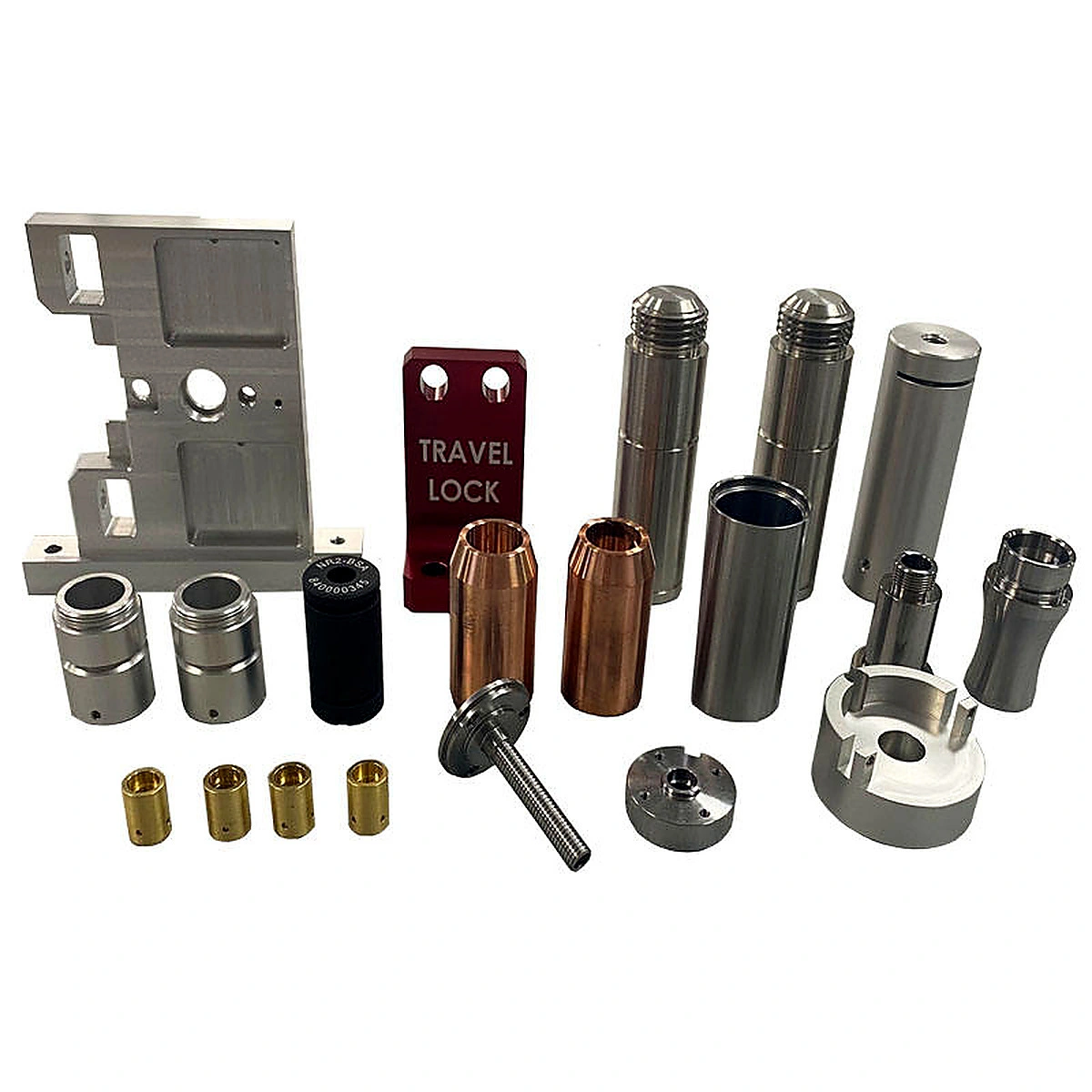
OEM Precision Metal Parts, Stainless Steel CNC Machining
Material-Specific CNC Machining Directions
| Material direction | Potential characteristics to consider | Information required before production |
|---|---|---|
| Stainless steel | Corrosion-related requirements, exposed hardware and durable interfaces | Grade, condition, corrosion environment and certificate need |
| Aluminum | Lightweight brackets, housings, sleeves, knobs and machined structures | Alloy, temper, weight target and finish |
| Titanium | Weight-sensitive or demanding application direction | Grade, heat input considerations, surface and application conditions |
| Brass | Machinability, conductivity, fittings and contrasting appearance | Alloy, conductivity, color and contact requirements |
| Carbon or alloy steel | Structural, shaft, threaded or wear-related components | Grade, hardness, heat treatment and surface protection |
| Engineering plastic | Insulating, low-friction or non-metallic component direction | Resin, temperature, load and dimensional stability |
Material names above are selectable project directions from the customer’s requested product description. The image alone does not identify the material of each part.
CNC Process Scope
| Process | Typical feature | Why it may be selected |
|---|---|---|
| CNC turning | Shafts, sleeves, bushings, threaded bodies, collars and round housings | Controls rotational profiles and diameters |
| CNC milling | Brackets, plates, pockets, flats, windows and irregular outlines | Creates non-round functional geometry |
| Drilling | Through holes, blind holes and cross holes | Adds mounting, locating or passage features |
| Boring and reaming | Internal bores and fitted holes | Supports internal dimensional requirements |
| Tapping and threading | Internal and external threads | Creates assembly and connection interfaces |
| Grooving and slotting | Retaining grooves, axial slots and relief details | Supports retention, adjustment and clearance |
| Knurling | Grip texture on knobs or cylindrical parts | Improves manual handling or identification |
| Chamfering | Hole entries, thread starts and external edges | Supports assembly and edge control |
| Deburring | Machined edges, holes and pockets | Improves handling and assembly readiness |
| Finishing | Polishing, anodizing, plating, coating or specified treatment | Meets appearance or functional surface requirements |
| Marking | Part number, logo, batch or text | Supports traceability and product identification |
OEM Manufacturing Workflow
| Stage | Main activity | Customer-facing result |
|---|---|---|
| 1 | Receive drawing, CAD, sample or BOM | Part reference and revision record |
| 2 | Review interfaces and critical dimensions | Clarification list and manufacturability notes |
| 3 | Confirm material family | Stainless steel, aluminum, titanium, brass or other direction |
| 4 | Plan turning, milling and secondary operations | Process route and quotation assumptions |
| 5 | Produce prototype or first article | Sample for fit and functional review |
| 6 | Confirm finish, marking and packing | Approved appearance and delivery instructions |
| 7 | Inspect agreed features | Dimensional, thread, bore and visual records |
| 8 | Release production version | Controlled drawing, sample or revision |
| 9 | Manufacture and pack | Part-number and batch-managed components |
| 10 | Maintain repeat-order data | More consistent future supply |
Precision and Inspection Points
| Inspection item | Possible focus | Why it matters |
|---|---|---|
| Overall dimensions | Length, diameter, thickness and profile | Confirms basic drawing compliance |
| Bore and fit | Internal diameter, depth, shoulder and fit zone | Supports mating components |
| Thread | Standard, pitch, major/minor diameter and engagement | Supports connection performance |
| Hole pattern | Diameter, location, center distance and countersink | Supports installation and alignment |
| Concentricity | Coaxial bores, shafts, sleeves and turned features | Supports rotation and fit |
| Runout | Rotating or long cylindrical components | Supports functional movement |
| Flatness | Plates, brackets, flange faces and mounting surfaces | Supports stable installation |
| Surface | Roughness, color, treatment and visible defects | Controls appearance and interface condition |
| Marking | Text, Logo, part number and location | Supports identification and traceability |
| Packing | Part number, quantity, batch and revision | Reduces mix-up risk in OEM assembly |
Customization Options
| Custom item | Possible direction | Customer input |
|---|---|---|
| Material | Stainless steel, aluminum, titanium, brass, steel, plastic or specified alloy | Grade and application environment |
| Turned geometry | Sleeves, bushings, shafts, posts, threaded bodies and collars | Section view, dimensions and critical fit |
| Milled geometry | Brackets, plates, pockets, slots, windows and shaped profiles | 3D CAD or detailed drawing |
| Threads | Internal/external, metric/inch or drawing-defined thread | Thread standard and mating part |
| Bores and holes | Through, blind, stepped, cross or patterned holes | Diameter, depth, location and tolerance |
| Surface | Machined, polished, anodized, plated, coated or colored | Standard, color reference or sample |
| Texture | Knurling, grip pattern or functional surface | Pattern, pitch and usable area |
| Marking | Logo, text, part number, batch or revision | Artwork and location |
| Inspection | Dimensional, thread, bore, appearance and assembly checks | Inspection plan and acceptance criteria |
| Packaging | Bulk, individual, tray, kit, label and batch separation | Packing instruction and BOM |
Applications
| Application | Suitable component direction | Project focus |
|---|---|---|
| Industrial equipment | Housings, shafts, bushings, brackets and threaded fittings | Fit, strength direction and serviceability |
| Automation and fixtures | Plates, clamps, locating parts, posts and sleeves | Alignment, repeatability and access |
| Fluid or pneumatic equipment | Threaded tubes, adapters, sleeves and fittings | Thread, bore, sealing face and passage |
| Electronics and instruments | Small housings, knobs, inserts and mounting parts | Clearance, appearance and controlled assembly |
| Travel or locking mechanisms | Marked plates, shafts, pins and locking-related components | Interface, actuation and identification |
| Repair and replacement | Sample-matched sleeves, bushings, covers and shafts | Reference matching and revision control |
| OEM assemblies | Coordinated sets of multi-material machined parts | BOM, traceability and repeat supply |
| Prototype development | First-article brackets, connectors, housings and fittings | Design validation and iteration |
FAQ
Q1. What are OEM precision metal parts?
OEM precision metal parts are drawing- or sample-based components manufactured for integration into an original equipment assembly. They may include brackets, sleeves, shafts, bushings, housings, fittings and inserts.
Q2. Can you machine stainless steel, aluminum, titanium and brass?
These materials can be reviewed as project-specific material directions. The exact alloy, temper or grade, machining requirements, finish and inspection criteria must be confirmed before production.
Q3. What is CNC stainless steel machining used for?
CNC stainless steel machining is used to produce components such as sleeves, shafts, housings, fittings, brackets and inserts when the project requires a stainless steel material direction. Final suitability depends on the selected grade and application environment.
Q4. Can the parts be made from customer drawings or samples?
Yes. A 2D drawing, 3D CAD file, sample or BOM can support quotation, process planning and production review. Critical fits are best controlled with dimensioned technical data.
Q5. Can one order combine different materials?
A project may include stainless steel, aluminum, titanium, brass or other specified materials across different part numbers. Each part should have a clear material and finish requirement in the BOM or drawing.
Q6. Are the copper-colored parts definitely brass?
No. A copper-colored appearance does not prove a brass material. The actual material must be confirmed through the customer specification or material documentation.
Q7. Can internal and external threads be customized?
Yes. Thread standard, diameter, pitch, length, engagement and mating component should be provided. Internal threads and external threads should be listed separately in the drawing or BOM.
Q8. Can small cylindrical inserts and bushings be produced?
Yes. The image shows small cylindrical parts, bushings and threaded inserts. Bore, outside diameter, length, fit, material and installation method should be defined.
Q9. Can the visible colors be matched?
Color matching can be discussed using a reference sample or color requirement. The final result depends on the substrate and selected process, such as anodizing, plating, coating or another treatment.
Q10. Can you add text or a product mark?
Marking can be reviewed for text, part number, logo, batch or revision. The visible TRAVEL LOCK text is treated as image content only and is not assumed to be the required customer marking.
Q11. Can you supply prototypes and small batches?
Prototype, first-article and small-batch production can be reviewed according to geometry, material, setup, inspection and quantity requirements.
Q12. What information is required for a quotation?
Provide a drawing, CAD model, sample or BOM, together with material, quantity, critical dimensions, tolerance, thread, finish, marking, inspection and packing requirements.
Q13. Does the image prove a specific tolerance or grade?
No. The image shows part forms and visible finishes only. It does not prove a numeric tolerance, material certificate, hardness, equipment accuracy or inspection result.
Q14. How are repeat OEM orders controlled?
Repeat orders can be managed through an approved drawing or sample, revision record, material specification, process notes, inspection points, marking and packing instructions.
Send your drawing, CAD model, sample or BOM to discuss OEM precision metal parts, CNC stainless steel machining and custom multi-material CNC parts in stainless steel, aluminum, titanium, brass or other specified materials.
The service supports 5 axis CNC machining for multi-face or angled access, plus milling, turning, drilling, boring and threading. It produces small aluminum CNC machined parts, prototypes, replacement parts and low-volume assemblies. Final grades, tolerances, finishes and inspection requirements are confirmed per project.