


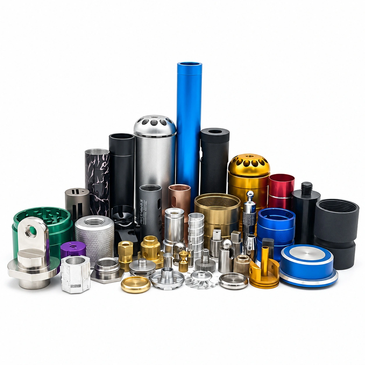
Custom Stainless Steel CNC Turning Parts & Waterjet Cutting
Visible Part Families
| Part family | Features visible or definable by drawing | Potential use |
|---|---|---|
| Threaded connectors | External threads, internal threads, shoulders and sealing faces | Adapters, fittings and mechanical connections |
| Stepped threaded bodies | Multiple diameters, thread sections and axial shoulders | Industrial interfaces and replacement parts |
| Flanged plugs | Circular flange, threaded boss and central bore | Mounting, sealing and connection assemblies |
| Slotted cylindrical housings | Outer cylinder, internal cavity and side slots | Covers, retaining bodies and equipment housings |
| Cup or sleeve components | Outer wall, internal bore and concentric seat | Spacers, guides, retaining and rotating interfaces |
| Multi-hole discs | Circular body, central opening and repeated holes | Fixtures, mounting plates and flow-related hardware |
| Spherical multi-port parts | Curved outer body with intersecting threaded openings | Valves, junctions or special fittings; function to confirm |
| Shafts and pins | Coaxial diameters, steps, grooves and end details | Motion, positioning and transmission |
| Rings and collars | Bore, outer diameter, shoulder and seating face | Alignment, spacing and retention |
| Compact adapters | Thread, bore, hex or round body and end transition | Equipment integration and maintenance |
![Custom Stainless Steel CNC Turning Parts & Waterjet Cutting 6]() Geometry and Feature Table
| Feature | What it means | Drawing information required |
|---|---|---|
| External thread | Thread on the outside of a shaft or fitting | Standard, nominal size, pitch, length and relief |
| Internal thread | Thread inside a bore or housing | Standard, depth, lead-in and bottom condition |
| Coaxial bore | Bore aligned with the turned centerline | Diameter, depth, runout and fit |
| Stepped diameter | Several diameters along one axis | Diameter sequence, shoulder position and tolerance |
| Flange | Wider locating or mounting section | Outside diameter, thickness, hole pattern and datum |
| Radial hole | Side hole through a cylindrical body | Location, angle, diameter and intersection |
| Slot or window | Open relief, vent, clamp or access feature | Width, length, depth and edge treatment |
| Counterbore/countersink | Recess for fastener or seating | Diameter, depth, angle and position |
| Multi-port body | Several holes or threads on different faces | Orientation, datum and assembly relationship |
| Surface transition | Chamfer, radius, groove or shoulder | Profile, size and affected edge |
Material Directions
The user-provided product description includes iron, stainless steel and carbon steel. The images show metallic parts but do not identify exact grades; the final selection must appear on the drawing or purchase specification.
| Material direction | Typical reason to consider | Example components |
|---|---|---|
| Stainless steel | Corrosion resistance and durable exposed surfaces | Threaded fittings, sleeves, adapters and housings |
| Carbon steel | Strength, rigidity and industrial structural use | Shafts, plugs, pins and load-bearing parts |
| General steel / iron-based material | Cost or mechanical requirement subject to grade | Brackets, sleeves and machinery components |
| Aluminum | Low weight and suitable machinability when specified | Covers, brackets, small housings and fittings |
| Brass | Machinability, conductivity or appearance | Small adapters, inserts and turned fittings |
| Engineering plastic | Insulation, low weight or low-friction function | Bushings, guides and non-conductive parts |
![Custom Stainless Steel CNC Turning Parts & Waterjet Cutting 7]() Turning, Milling and Waterjet Process Scope
| Process | Best suited to | Possible output |
|---|---|---|
| CNC turning | Coaxial parts, shafts, sleeves, rings and threaded bodies | Round or rotational components |
| CNC milling | Flats, pockets, slots, holes and irregular faces | Blocks, brackets and secondary features |
| Waterjet cutting | Suitable flat sheet or plate profiles | Cut blanks, plates and profile components |
| Drilling and boring | Through holes, blind holes and precision bores | Assembly and mating interfaces |
| Threading and tapping | Internal or external threads | Fastening, adjustment and connection features |
| Turn-mill combination | Turned body with radial holes, flats or slots | Multi-feature components |
| Deburring | Sharp edges and cutting burrs | Safer handling and cleaner assembly |
| Surface treatment | Appearance, corrosion or functional finish | Project-specific finished parts |
Waterjet Cutting and Secondary Machining
Waterjet cutting is not automatically suitable for every metal part. It is generally reviewed when the customer needs a flat profile from sheet or plate before additional operations. The project should clarify whether the cut blank will receive drilling, tapping, milling, turning, grinding, deburring or surface treatment afterward.
| RFQ question | Why it matters |
|---|---|
| What is the material grade? | Cutting behavior and downstream machining depend on the material. |
| What is the plate or sheet thickness? | Determines whether waterjet is an appropriate route. |
| Is the profile flat or rotational? | Flat profiles may suit cutting; rotational forms may require turning. |
| Are edge conditions critical? | Kerf, taper, burr and post-processing requirements should be defined. |
| Are holes included in the cut? | Small holes may need drilling or secondary machining. |
| What are the final tolerances? | Cutting tolerance and finished machining tolerance are different. |
| Is a secondary operation required? | The complete route should include milling, turning or deburring if needed. |
Drawing-to-Part Workflow
| Stage | Work activity | Customer-facing output |
|---|---|---|
| 1 | Receive drawing, CAD file or sample | Reference and revision record |
| 2 | Review material and geometry | Questions about grade, thickness and features |
| 3 | Select process route | Turning, milling, waterjet or combined proposal |
| 4 | Confirm critical features | Threads, bores, flanges, slots and hole locations |
| 5 | Prepare quotation | Project-based price and production discussion |
| 6 | Produce prototype or first article | Part for fit and functional review |
| 7 | Perform in-process checks | Feature and dimension monitoring |
| 8 | Complete final inspection | Agreed dimensional and visual checks |
| 9 | Apply finish and pack | Protection, labels and part identification |
| 10 | Ship and maintain revision | Reference for repeat orders |
Customization Services
| Custom item | What can be customized | Customer input |
|---|---|---|
| Part geometry | Fittings, shafts, sleeves, flanges, rings, housings and adapters | 2D drawing, 3D CAD or sample |
| Threads | Internal/external thread form, pitch, length and relief | Thread callout and mating data |
| Bores | Through bore, blind bore, counterbore and stepped bore | Diameter, depth, fit and datum |
| Milling details | Flats, pockets, slots, radial holes and mounting faces | Feature locations and orientation |
| Cut profile | Waterjet blank profile or plate contour | DXF/CAD geometry and thickness |
| Material | Stainless steel, carbon steel, iron-based material, aluminum, brass or plastic | Grade and application |
| Finish | As-machined, polished, brushed, plated, coated or other specified finish | Standard or reference sample |
| Marking | Part number, revision, batch code or logo | Artwork and location |
| Quantity | One prototype, small batch or repeat production | Quantity and target date |
| Packaging | Individual protection, tray, bag, label and carton mark | Packing specification |
Applications
| Application | Example parts | Project focus |
|---|---|---|
| Industrial machinery | Flanges, housings, plugs, sleeves and adapters | Strength, fit and serviceability |
| Fluid or gas equipment | Threaded bodies, fittings and multi-port parts | Thread, sealing and material confirmation |
| Automation | Shafts, collars, clamps and mounting parts | Positioning and repeatability |
| Tooling and fixtures | Plates, discs, inserts and slotted parts | Datum, clamping and rigidity |
| Maintenance and repair | Replacement connectors, sleeves and custom adapters | Sample matching and revision control |
| Equipment enclosures | Cylindrical covers, cups and machined housings | Interface, appearance and fit |
| Product development | Prototype turning, milling and cut blanks | Design validation and iteration |
| General OEM supply | Drawing-defined metal components | Revision, inspection and repeat orders |
Quality and Inspection Information
| Quality item | What should be specified | Purpose |
|---|---|---|
| Material certificate | Grade and required material documentation | Confirms material identity |
| Drawing revision | Approved file and change level | Prevents outdated production |
| Thread verification | Thread gauge or mating-part check | Supports assembly reliability |
| Bore and shaft fit | Clearance, transition or interference fit | Controls installation behavior |
| Flatness and profile | Especially relevant to cut plates and milled faces | Supports mounting and sealing |
| Visual finish | Burr, scratch, discoloration and treatment standard | Controls delivered appearance |
| First article | Prototype or first-piece review | Confirms design before batch work |
| Final inspection | Agreed dimensions and records | Provides project evidence |
| Packing traceability | Part number, revision and batch label | Supports repeat supply |
FAQ
Q1. What are custom stainless steel CNC turning parts?
They are stainless steel components produced to a customer drawing, CAD file or approved sample. Examples include threaded fittings, stepped bodies, shafts, sleeves, rings, plugs, adapters and housings.
Q2. Can you machine carbon steel and iron-based materials?
Carbon steel and other iron-based materials can be reviewed according to the grade, heat condition, geometry, corrosion environment and final application. The exact material must be stated in the drawing or purchase specification.
Q3. What does a small metal CNC milling service include?
It can include small blocks, plates, brackets, slots, flats, pockets, holes, clamps, inserts and secondary milling features on turned or cut components. Feasibility depends on size, access, tolerance and material.
Q4. Can waterjet cutting be combined with CNC machining?
Yes. A waterjet-cut blank may be followed by drilling, tapping, milling, turning, deburring or surface treatment when the drawing requires additional operations. The complete route should be reviewed as one project.
Q5. Is waterjet cutting suitable for threaded round parts?
Usually, a threaded round part is more naturally reviewed for CNC turning. Waterjet cutting may be suitable for a flat blank or plate profile that will receive later machining. The final process depends on geometry and thickness.
Q6. Can you make internal and external threads?
Yes. Internal and external threads can be reviewed, including threaded fittings, plugs, sleeves and adapters. Thread standard, pitch, depth, length and mating information are required.
Q7. Can you produce parts from a physical sample?
A physical sample can support feasibility review, replacement-part development or reverse-engineering discussion. A drawing or CAD file is recommended for critical tolerances and repeat orders.
Q8. What materials can be customized?
The stated product direction includes stainless steel, carbon steel and iron-based materials. Aluminum, brass, engineering plastic and other materials may also be discussed when suitable for the application and process.
Q9. Can you machine flanges, sleeves and multi-port parts?
Yes. The images show flanges, sleeves, rings, cylindrical bodies and a spherical body with multiple openings. Final port orientation, thread, bore, sealing and assembly requirements must be defined by drawing.
Q10. What information is needed for quotation?
Provide the drawing or CAD file, material grade, quantity, critical tolerances, threads, bores, surface finish, inspection requirements, application and target delivery plan.
Our custom CNC machined metal parts can be developed from drawings, CAD files or samples. The CNC machining service for aluminum and stainless steel supports housings, fittings, shafts and assembly hardware. Custom CNC turning and milling parts can combine rotational features with holes, flats, pockets, slots and mounting faces. Final material grades, tolerances, finishes and inspection requirements are confirmed per project.
Our service produces anodized aluminum CNC parts and CNC machining prototype parts, plus stainless steel parts, CNC turning, milling and Swiss-type machining. The images show drawing review, raw-material procurement, FAI, machining, IPQC, dimensional inspection, batch inspection, surface treatment, final inspection and delivery. Exact grades, tolerances, finishes and schedules are confirmed per project.