


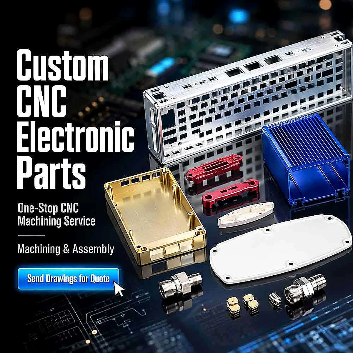
CNC Electronic Enclosure, Custom Machined Prototype Parts
Design Features
| Design feature | Possible customization | Why it matters |
|---|---|---|
| External envelope | Length, width, height, corner treatment and cover relationship | Fits the target equipment and installation space |
| Internal cavity | Pocket, recess, standoff area and component clearance | Supports PCB, connector or module placement |
| Openings | Rectangular windows, circular holes, slots and cable access | Accommodates ports, switches, displays and wiring |
| Ventilation pattern | Repeated openings, slots or ribbed surfaces | Supports the specified airflow concept; performance requires validation |
| Mounting points | Bosses, threaded holes, through holes and brackets | Secures the enclosure or internal components |
| Cover interface | Screw fastening, slide fit, locating edge or assembly interface | Controls service access and repeatable fit |
| Panel interface | Flat face, recessed area, display opening or label zone | Supports user-facing or equipment-facing components |
| Connector interface | Threaded, bored, keyed or bracket-mounted feature | Matches the selected connector or cable hardware |
| Surface direction | Machined, polished, anodized, coated, colored or marked | Defines appearance and identification |
| Assembly reference | Datum, alignment feature, insert or fastener location | Supports repeatable assembly |
CNC Electronic Enclosure Machining Scope
| Process | Typical enclosure feature | Project result |
|---|---|---|
| CNC milling | Outer profile, pockets, recesses, windows and flat faces | Creates the enclosure geometry |
| Drilling | Mounting holes, cable holes and blind holes | Adds installation and routing features |
| Tapping | Internal threaded holes and fastening interfaces | Supports cover and component fastening |
| Slotting | Ventilation slots, guide channels and cable passages | Adds linear access and positioning features |
| Pocketing | Internal cavities, component seats and recessed panels | Creates controlled internal space |
| Boring or reaming | Precision bores and connector openings | Supports fitted interfaces |
| Chamfering | Panel edges, hole entries and assembly lead-ins | Reduces sharp edges and supports fit |
| Deburring | Machined openings, pockets and external edges | Improves handling and assembly readiness |
| Surface finishing | Polishing, anodizing, coating, plating or specified process | Meets approved appearance direction |
| Marking | Logo, part number, text, revision or warning mark | Supports identification and traceability |
| Assembly preparation | Sorting, hardware matching and component grouping | Helps move parts into an assembly process |
Machining & Assembly Service
The image explicitly presents Machining & Assembly and One-Stop CNC Machining Service. The page can therefore position the supplier as a coordinated project partner while keeping the actual assembly scope subject to confirmation.
| Service stage | Work activity | Customer input or output |
|---|---|---|
| Design review | Review enclosure, cover, panel, port and mounting features | Drawing, CAD or sample |
| DFM discussion | Identify wall thickness, tool access, internal corners and assembly sequence | Clarification list |
| Prototype machining | Produce CNC rapid prototype parts for fit and layout review | Prototype enclosure or component |
| Surface and marking | Coordinate color direction, coating, label or part marking | Approved sample or finish direction |
| Hardware preparation | Match screws, inserts, connectors or small hardware where specified | BOM and component list |
| Assembly trial | Check cover fit, component placement and mounting sequence | Trial assembly feedback |
| Inspection | Check critical dimensions, openings, threads and visual finish | Inspection record as agreed |
| Packing | Separate parts by number, assembly group or revision | Assembly-ready packing |
| Repeat production | Preserve approved data and revision information | Controlled repeat order |
Rapid Prototype Workflow
| Step | Prototype activity | Decision supported |
|---|---|---|
| 1 | Receive drawing, CAD, sample or concept | Confirm the design reference |
| 2 | Review enclosure layout and interfaces | Identify openings, covers and mounting points |
| 3 | Confirm material and finish direction | Select a suitable prototype route |
| 4 | Machine the first prototype | Check physical form and component fit |
| 5 | Trial assembly | Check cover, panel, connector and hardware relationship |
| 6 | Record design changes | Establish a controlled revision |
| 7 | Produce updated sample or pilot batch | Validate the revised design |
| 8 | Release production data | Prepare for repeat or small-batch supply |
Materials and Surface Directions
The image shows silver, blue, red, gold, black and white appearances. These colors are visual references only and do not prove the substrate or finishing process.
| Material direction | Potential use | Confirmation required |
|---|---|---|
| Aluminum | Lightweight enclosures, panels, covers and brackets | Alloy, temper, wall thickness and finish |
| Stainless steel | Durable panels, fittings or exposed hardware | Grade, condition, corrosion environment and surface |
| Carbon or alloy steel | Brackets, fixtures or structural hardware | Grade, hardness, treatment and corrosion protection |
| Brass or copper alloy | Small fittings, connectors or conductive hardware | Alloy, conductivity and contact requirement |
| Engineering plastic | Insulating covers, spacers or non-metallic housings | Resin, temperature and dimensional stability |
| Other specified material | Application-specific electronic component | Grade, supply form and technical specification |
| Finish direction | Possible purpose | Data to provide |
|---|---|---|
| As-machined | Controlled machined appearance | Roughness and allowable tool marks |
| Anodized or colored | Color and surface direction for suitable substrates | Substrate, color reference and durability |
| Polished | Smoother or brighter visual finish | Target appearance or approved sample |
| Plated or coated | Corrosion, wear or appearance requirement | Process, thickness and performance |
| Marked or labeled | Part identification or interface guidance | Text, logo, location and method |
Customer Inputs for Custom Electronic Parts
| Input | Information to include | Why it is needed |
|---|---|---|
| 2D drawing | Dimensions, tolerances, datum and notes | Defines the manufacturing target |
| 3D CAD | Solid model, openings, cavities and assembly context | Clarifies complex geometry |
| PCB or module envelope | Keep-out area, connector location and mounting holes | Controls internal and external fit |
| Interface list | Ports, cables, switches, displays and fasteners | Defines opening and access requirements |
| Assembly BOM | Part numbers, hardware and sequence | Coordinates machining and assembly |
| Material and finish | Substrate, color, coating and appearance sample | Avoids ambiguous surface assumptions |
| Prototype quantity | Sample, pilot or small batch requirement | Supports route and quotation review |
| Inspection plan | Critical dimensions, fit and visual criteria | Defines acceptance focus |
| Packing method | Individual, kit, assembly group, label and revision | Protects parts and prevents mix-up |
Applications
| Application | Suitable visible direction | Project focus |
|---|---|---|
| Electronic equipment | Custom enclosures, panels, covers and connector parts | Internal clearance, access and appearance |
| Control units | Box housings, mounting plates, rails and hardware | Interface layout and assembly sequence |
| Test fixtures | Brackets, covers, guide parts and machined supports | Repeatability, access and serviceability |
| Instruments | Small housings, panels, knobs and connector interfaces | Visibility, fit and controlled installation |
| Embedded devices | Compact covers, brackets and custom openings | Space use, cable routing and assembly |
| Prototype products | CNC rapid prototype parts and trial enclosures | Design validation and revision speed |
| Industrial electronics | Panels, housings, fittings and mounting structures | Equipment integration and maintenance |
| OEM assemblies | Coordinated machined parts, hardware and packing | BOM control, traceability and repeat supply |
Inspection and Acceptance Directions
| Inspection item | Possible check | Customer value |
|---|---|---|
| Enclosure dimensions | Length, width, height, wall thickness and profile | Confirms equipment fit |
| Opening geometry | Window, slot, port, hole and repeated pattern | Supports interface alignment |
| Cover fit | Contact edge, locating feature, gap and fastening position | Supports assembly and service access |
| Mounting points | Hole location, thread, boss and bracket position | Secures internal or external components |
| Internal clearance | Cavity, keep-out and component seating | Reduces interference risk |
| Surface appearance | Color, coating, marks, burrs and visible defects | Controls presentation and handling |
| Connector interface | Bore, thread, key, bracket and cable path | Supports selected hardware |
| Assembly check | Sequence, fastening and component relationship | Finds fit issues before repeat supply |
| Marking and packing | Part number, revision, group and quantity | Supports OEM traceability |
FAQ
Q1. What is a CNC electronic enclosure?
A CNC electronic enclosure is a drawing-based housing, panel, cover or structural part machined for electronic equipment, control assemblies, instruments or custom devices. The final geometry depends on the internal components and interfaces.
Q2. Can you make custom machined enclosures from CAD files?
Yes. A 3D CAD model, 2D drawing, sample or assembly BOM can be used for design review, quotation and prototype planning. Critical fits should be defined with dimensioned technical data.
Q3. What are CNC rapid prototype parts used for?
They are used to check physical form, opening layout, cover fit, connector position, component clearance and assembly sequence before a pilot or production order.
Q4. Can the enclosure include holes, slots and repeated openings?
Yes. The image shows a panel with repeated rectangular openings and other parts with visible holes and access features. The opening size, pitch, depth, edge condition and intended function must be defined in the drawing.
Q5. Can you machine both the housing and its matching cover?
Matching housings and covers can be reviewed as a paired project. The interface, locating features, fastening method, gap and revision must be controlled together.
Q6. Can machining and assembly be supplied together?
The image explicitly presents Machining & Assembly. Assembly scope can include grouping, hardware matching, trial fitting or specified component installation when the BOM and assembly instructions are provided.
Q7. Can you add connector openings and cable access features?
Yes. Connector bores, rectangular ports, cable openings, mounting holes and guide slots can be defined according to the selected components and assembly layout.
Q8. Can colors in the image be matched?
Color or finish matching can be discussed using a reference sample or color requirement. The final result depends on the substrate and selected process; the image alone does not establish a standard finish.
Q9. Does the image prove an IP rating or EMI shielding performance?
No. The image shows enclosure forms and visible openings but does not prove IP protection, EMI shielding, thermal performance or certification. Those requirements need dedicated design and validation criteria.
Q10. What information is needed for a quote?
Send drawings, CAD files, samples or a BOM, together with material, wall thickness, openings, tolerances, finish, marking, quantity, inspection and assembly requirements.
Q11. Can prototypes move into small-batch production?
Yes. After prototype fit and design review, the approved revision, material, finish, inspection points, assembly scope and packing method can be used for pilot or repeat production.
Q12. Can labels or product text be added?
Text, logos, part numbers, revision marks and label zones can be discussed. The image’s visible wording is treated as reference artwork only and is not assumed to be the customer’s required text.
Q13. Can small brackets and connector hardware be supplied with the enclosure?
A project may include matching brackets, rails, inserts, connectors or small hardware when the BOM, drawings and supply scope are defined.
Q14. Does CNC automatically mean a specific precision level?
No. CNC describes a controlled machining method, but numeric tolerance and inspection requirements must be stated in the drawing and verified according to the agreed inspection plan.
Send your drawings, CAD model, sample or BOM to discuss a CNC electronic enclosure, custom machined enclosures and CNC rapid prototype parts with machining, finishing, marking, packing and assembly support.
The service supports 5 axis CNC machining for multi-face or angled access, plus milling, turning, drilling, boring and threading. It produces small aluminum CNC machined parts, prototypes, replacement parts and low-volume assemblies. Final grades, tolerances, finishes and inspection requirements are confirmed per project.